RT-Thread Complementary Filter (STM32 + 6-axis IMU)
Author: Wu Han
I’ve recently been exploring the prediction aspect of autonomous driving, which can utilize the EKF (Extended Kalman Filter) to merge data from various sensors, such as IMU, Lidar, and GNSS, to provide more precise state predictions.
I have a 6-axis IMU on my development board and initially planned to experiment with the Kalman Filter. However, it is better suited for 9-axis sensors, where a 3-axis magnetometer is fused with a 6-axis sensor (3-axis Accel + 3-axis Gyro).
For an MCU with only a 6-axis IMU, a lightweight Complementary Filter is more appropriate. It employs a 3-axis gyroscope and a 3-axis accelerometer to estimate the development board’s orientation (Pitch, Roll, Yaw).
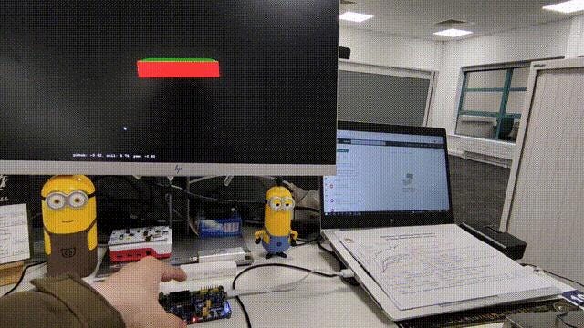
The process is straightforward: Start by using RT-Thread’s icm20608 package to read data from the Gyroscope and Accelerometer. Then, calculate the estimated angles separately and use the Complementary Filter to merge the two angle estimates and calibrate them. The core algorithm is concise, with only 7 lines of code. Finally, transmit the data to your computer via a serial port and visualize it using Python + OpenGL.
Check out our Github page for more information: https://link.zhihu.com/?target=https%3A//github.com/wuhanstudio/stm32-imu-filter
Inertial Measurement Unit Sensor
First, let’s discuss how to process raw sensor values from the I2C bus to determine acceleration and angular velocity.
A 6-axis IMU can measure gravitational acceleration along the x, y, and z axes, as well as angular velocity around each axis. For instance, if the development board is stationary on a desk, it will detect gravitational acceleration along the z-axis.
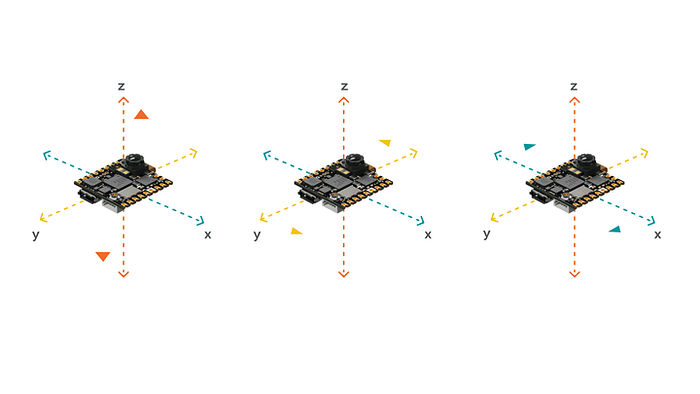
Measuring acceleration across three axes
Naturally, if the development board remains still, the rotational velocity around each of the three axes will be zero.
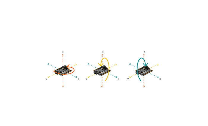
Measuring angular velocity across three axes
The sensor’s output is a 16-bit digital signal from the ADC, which must be converted to gravitational acceleration (g). You can select the measurement range (±2�,±4�,±8�), with the default being ±2�. This maps the sensor’s 16-bit output [−215,215) to [-2g, 2g), resulting in 215LSB / 2�=16384 LSB/�. This is the Sensitivity Scale Factor specified in the icm20608 chip manual.

As a result, the raw int16 acceleration data is divided by 16384 within the code.
double aSensitivity = 16384;
accel_x = accel_x / aSensitivity;
accel_y = accel_y / aSensitivity;
accel_z = accel_z / aSensitivity;In the same way, we can figure out the angular speed (which can be measured within a range of plus or minus 250 degrees per second): 215 divided by 250 equals 131.072.

So, in the code, we take the initial int16 data for the angular speed and divide it by 131.
double gSensitivity = 131;
gyrX = gyro_x / gSensitivity;
gyrY = gyro_y / gSensitivity;
gyrZ = gyro_z / gSensitivity;By doing this, we change the int16 raw data that the ADC puts out into units of acceleration (g) and rotational speed (degrees per second).
Complementary Filter
We can take the measurements of acceleration and rotational speed and combine them using a complementary filter to get a better prediction of posture.
We use the coordinate system shown in the picture below. The angle of rotation around the x-axis is called roll, the rotation around the y-axis is pitch, and the rotation around the z-axis is yaw. If it rotates counterclockwise, it’s positive. If it rotates clockwise, it’s negative.
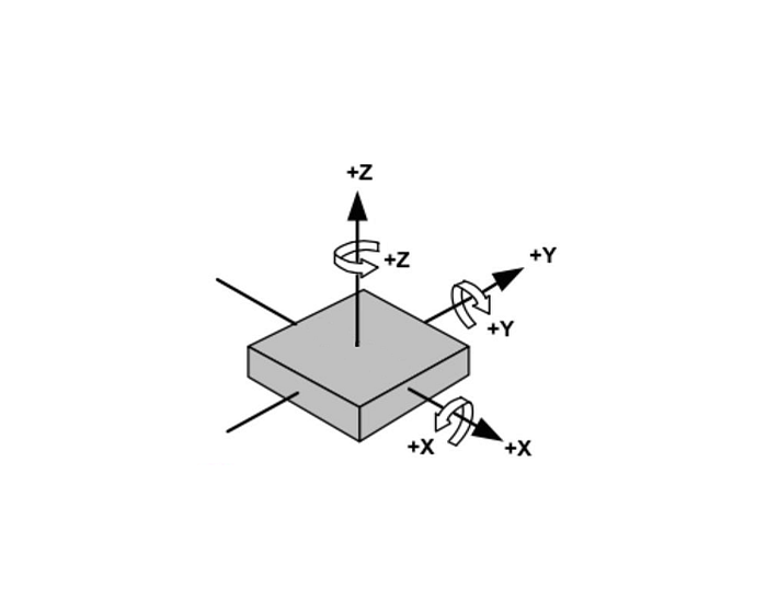
Gyroscope Estimates Posture
The gyroscope takes the measurement of the rotational speed at that moment, so to estimate the position, we add up the measurements over time. For instance, if we measure the rotational speed every 100ms, we can multiply the rotational speed by the time to get the rotational angle.
// angles based on gyro (deg/s)
gx = gx + gyrX * TIME_STEP_MS / 1000;
gy = gy + gyrY * TIME_STEP_MS / 1000;
gz = gz + gyrZ * TIME_STEP_MS / 1000;
Because there’s a lot of noise around, the measurements from the gyroscope can be a bit all over the place. These little bits of noise add up over time and can make the position start to drift.
Take the picture below, for instance. After a while, even though the development board isn’t moving, the position that the gyroscope on the right estimates can’t get back to where it started. This happens because of all the little errors adding up over time.

Accelerometer Estimates Posture
We don’t have to add up the measurements from the accelerometer. We can just take the arctan of the angle of acceleration at that moment to find the angle:

// angles based on accelerometer
ax = atan2(accelY, accelZ) * 180 / M_PI;                                     // roll
ay = atan2(-accelX, sqrt( pow(accelY, 2) + pow(accelZ, 2))) * 180 / M_PI;    // pitch
Even if our development board spins around the z-axis, gravity always pulls it toward the ground. So, when the development board isn’t moving, we can’t use gravity to figure out the angle of rotation around the z-axis (yaw). That means we only calculate roll and pitch, and the final angle of rotation around the z-axis (yaw) will have errors that add up over time.
Complementary Filter
We have to use two measurements because: the rotational speed is pretty accurate over a short time, but because of all the noise around, it can start to move randomly and drift off course. The acceleration might not be spot on over a short time, but it’ll stay steady in the end.
So we can use each measurement to make up for what the other one lacks. We add them together to get a better estimate.
// complementary filter
gx = gx * 0.96 + ax * 0.04;
gy = gy * 0.96 + ay * 0.04;
For a little while, we rely on the measurement of rotational speed from the gyroscope (with a weight of 0.96). But over time, the drift that happens because of all the noise around us is slowly fixed by the accelerometer (with a weight of 0.04).
Summary
To sum it up, there are really only 7 lines of code that matter. We start by using acceleration to figure out posture, then we use rotational speed to do the same thing. In the end, we add them together using a complementary filter.
// angles based on gyro (deg/s)
gx = gx + gyrX * TIME_STEP_MS / 1000;
gy = gy + gyrY * TIME_STEP_MS / 1000;
gz = gz + gyrZ * TIME_STEP_MS / 1000;
// angles based on accelerometer
ax = atan2(accelY, accelZ) * 180 / M_PI; // roll
ay = atan2(-accelX, sqrt( pow(accelY, 2) + pow(accelZ, 2))) * 180 / M_PI; // pitch
// complementary filter
gx = gx * 0.96 + ax * 0.04;
gy = gy * 0.96 + ay * 0.04;
